A stilling basin exists to destroy energy. Water falling from a spillway crest, or shooting through a sluice gate, arrives at the basin floor carrying enormous kinetic energy. The basin’s job is to convert that directed energy into turbulence, then dissipate the turbulence before the water reaches the downstream channel.
The concrete that forms the stilling basin floor, walls, baffle blocks, and end sill absorbs this energy transfer directly. It is pounded by turbulent flow, scoured by sediment, impacted by boulders, and subjected to cavitation at every surface irregularity. No other concrete in the dam project faces comparable abuse.
Despite this, stilling basin concrete is often treated as an afterthought during design. The hydraulic engineer designs the basin geometry; the structural engineer sizes the slab thickness and anchorage; but the concrete technology consultant is rarely consulted on material selection, mix design, and placement practices specific to this extreme environment. The result is premature erosion, expensive repairs, and in severe cases, undermining of the basin slab that threatens the dam’s stability.
The Hydraulic Environment
Understanding what stilling basin concrete must withstand begins with understanding the hydraulic forces acting on it.
Energy Dissipation and Impact
When water falls from a spillway crest to a stilling basin, it converts potential energy to kinetic energy. For a 50-metre head, the theoretical velocity at the basin floor exceeds 30 m/s. The hydraulic jump that forms in the basin converts this supercritical flow to subcritical flow, but the conversion is violent.
The forces involved are substantial. Dynamic pressures on the basin floor during a hydraulic jump can fluctuate between 2 and 10 times the hydrostatic pressure. Baffle blocks, which project above the basin floor to assist energy dissipation, experience concentrated impact loads that can exceed 500 kPa.
Abrasion
Indian rivers carry heavy sediment loads. The Himalayan rivers feeding many of India’s hydroelectric projects transport sand, gravel, and boulders during monsoon floods. This sediment, accelerated to velocities of 10 to 30 m/s, acts as a natural abrasive against the concrete surface.
The abrasion rate depends on four factors:
- Flow velocity. Abrasion increases roughly with the cube of velocity. Doubling the velocity increases abrasion eightfold.
- Sediment concentration and hardness. Quartz sand (Mohs hardness 7) is far more abrasive than limestone silt (Mohs hardness 3).
- Concrete surface quality. Laitance, surface voids, and poorly finished surfaces erode first, creating irregularities that accelerate further damage.
- Aggregate quality. When the cement paste erodes, aggregate particles are exposed. If the aggregate is weak or poorly bonded, particles dislodge, deepening the erosion.
The ASTM C1138 underwater abrasion test provides a laboratory method for comparing the abrasion resistance of different concrete mixes under simulated hydraulic conditions.
Cavitation
Cavitation is the most destructive mechanism acting on stilling basin concrete. It occurs wherever the flow boundary has an irregularity: a protruding construction joint, a surface void, a damaged baffle block edge, or even a misaligned formwork panel.
The physics are well understood. Water flowing at high velocity over an irregularity separates from the surface, creating a zone where the absolute pressure drops below the vapour pressure of water (approximately 2.3 kPa at 20 degrees Celsius). Vapour bubbles form in this low-pressure zone. When these bubbles are carried downstream to a region of higher pressure, they collapse asymmetrically, generating micro-jets and shock waves with localised pressures exceeding 1,000 MPa.
No concrete can resist cavitation indefinitely. The strategy is therefore twofold: design the concrete surface to minimise cavitation inception (smooth profiles, well-aligned joints, no protrusions), and design the concrete material to resist damage when cavitation does occur. This challenge is closely related to spillway concrete abrasion and cavitation resistance, where the same mechanisms act on the chute surface upstream of the basin.
The USBR has published extensive research on cavitation damage in hydraulic structures, establishing that cavitation inception typically begins at flow velocities above 12 m/s over surface irregularities of 6 mm or more.
Concrete Material Selection
Aggregate Requirements
Aggregate selection for stilling basin concrete differs significantly from mass concrete aggregate selection. The priorities shift from thermal performance and economy to hardness, density, and bond strength.
| Property | Mass Concrete (dam body) | Stilling Basin Concrete |
|---|---|---|
| Maximum aggregate size | 75-150 mm | 20-40 mm |
| Los Angeles abrasion value | Less than 40% | Less than 20% |
| Aggregate crushing value | Less than 30% | Less than 20% |
| Preferred rock type | Any meeting spec | Granite, basalt, trap rock |
| Shape requirement | Standard | Cubical (flakiness less than 15%) |
| Specific gravity | 2.5+ | 2.7+ preferred |
The smaller maximum aggregate size in stilling basin concrete serves two purposes. First, it produces a smoother surface finish with fewer voids, reducing cavitation risk. Second, it reduces the size of the weakest link: the interfacial transition zone (ITZ) around each aggregate particle, which is where erosion-induced aggregate pullout begins.
Per IS 383:2016, aggregates for hydraulic structures must satisfy additional requirements for soundness and alkali reactivity beyond what is specified for ordinary structural concrete.
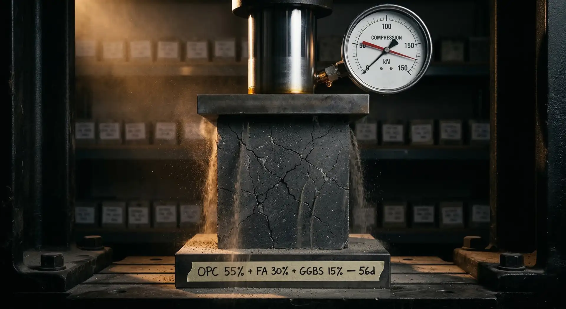
Cement and Cementitious Materials
The cementitious system for stilling basin concrete must produce a dense, low-permeability paste matrix with high early and ultimate strength. The mix design approach differs fundamentally from mass concrete proportioning.
Portland Pozzolana Cement (PPC) or OPC + fly ash is the standard binder for most dam components. For stilling basins, the fly ash content should be limited to 20 to 25%, lower than the 30 to 40% used in mass concrete. The reason is simple: stilling basins need high early strength to resist erosion from the first flood season, and high fly ash content delays strength gain. For a broader view of SCM strategies in dam concrete, the trade-offs between durability, thermal control, and early strength are explored in detail.
Silica fume at 5 to 8% by weight of cementitious material is strongly recommended for stilling basin concrete. Silica fume particles (0.1 to 0.2 micron diameter) fill the pores in the cement paste and react with calcium hydroxide to produce additional calcium silicate hydrate (C-S-H), the gel that gives concrete its strength. The result is a denser, harder, less permeable paste that resists abrasion and cavitation better than plain OPC concrete.
ACI 234R provides comprehensive guidance on the use of silica fume in concrete, including its effects on abrasion resistance and durability in hydraulic structures.
Mix Design Parameters
A typical stilling basin concrete mix design targets the following parameters:
| Parameter | Target Value |
|---|---|
| Compressive strength (28 days) | 40-50 MPa |
| Water-cementitious ratio | 0.35-0.40 |
| Total cementitious content | 380-420 kg/m³ |
| Silica fume content | 5-8% of cementitious |
| Fly ash content | 15-20% of cementitious |
| Maximum aggregate size | 20-25 mm |
| Slump | 75-100 mm (or SCC for complex geometry) |
| Air content (if freeze-thaw exposure) | 5-7% |
| Abrasion resistance (ASTM C1138) | Less than 2.0% mass loss at 72 hours |
The water-cementitious ratio is the single most important parameter for abrasion resistance. Research published by the USBR and ACI Committee 210 has consistently shown that abrasion resistance improves dramatically as the w/c ratio decreases below 0.45. Every 0.05 reduction in w/c ratio can reduce abrasion loss by 15 to 25%.
Fibre Reinforcement
Steel fibres (30 to 50 kg/m³) or synthetic macro-fibres (4 to 8 kg/m³) added to stilling basin concrete provide several benefits:
- Impact resistance. Fibres bridge micro-cracks, increasing the energy required to fracture the concrete under dynamic loading.
- Crack control. Fibres reduce the width and frequency of shrinkage and thermal cracks, which are initiation points for cavitation and erosion.
- Spalling resistance. Fibre-reinforced concrete resists the progressive surface spalling that occurs under cavitation loading.
- Post-crack toughness. Even after cracking, the concrete maintains residual load-carrying capacity, preventing sudden failure of baffle blocks and end sills.
However, fibres must not compromise the surface finish. The surface of stilling basin concrete must be smooth and free from protruding fibres that could initiate cavitation. This requires careful finishing techniques and appropriate fibre lengths (30 to 50 mm for steel fibres).
Placement and Construction Practices
Surface Finish Requirements
The surface quality of stilling basin concrete is arguably more critical than its compressive strength. A 50 MPa concrete with a rough, irregular surface will suffer more cavitation damage than a 40 MPa concrete with a smooth, well-finished surface.
Surface tolerances for stilling basin concrete should meet or exceed:
| Feature | Tolerance |
|---|---|
| Surface flatness (under 3 m straightedge) | Plus or minus 3 mm |
| Joint alignment (step between adjacent pours) | Less than 3 mm |
| Surface void diameter | Less than 3 mm |
| Surface void depth | Less than 3 mm |
| Chamfer on all edges and corners | 10-15 mm minimum |
Achieving these tolerances requires high-quality formwork (steel or high-grade plywood), skilled finishing crews, and post-strip inspection with immediate repair of any deficiencies.
Formwork Considerations
Stilling basin concrete is typically placed in lifts of 1.5 to 3.0 metres against formed surfaces. The formwork must be:
- Rigid. Deflection under concrete pressure must not create surface irregularities exceeding 3 mm. Steel formwork is preferred for critical surfaces.
- Watertight. Mortar leakage through form joints creates fins that become cavitation initiation points.
- Smooth. Form surface condition directly transfers to the concrete surface. Worn or damaged form panels must be replaced.
- Precisely aligned. Adjacent panels must produce a continuous surface without steps or offsets.
Concrete Placement and Compaction
The high cementitious content and low w/c ratio of stilling basin concrete make it more cohesive and less workable than mass concrete. Placement requires:
- Internal vibration. Immersion vibrators with a minimum frequency of 12,000 vibrations per minute. Vibration duration at each insertion point should be 15 to 30 seconds, ensuring complete compaction without segregation.
- Layer thickness. Each vibrated layer should not exceed 450 mm for 50 mm diameter vibrators. Thinner layers (300 mm) are advisable for heavily reinforced zones around baffle blocks.
- Revibration. For large pours, revibration of the previously placed layer (within 30 minutes of initial placement) improves the interface bond and reduces the risk of cold joint formation.
Curing
Stilling basin concrete requires extended curing: a minimum of 14 days of continuous moist curing, with 28 days preferred. Curing compounds should not be used on hydraulic surfaces because they can peel or flake, creating surface irregularities. Water curing (ponding, wet hessian, or continuous misting) is the standard method.
Baffle Blocks and End Sills
Baffle blocks (also called chute blocks or dentated sills) are the elements within the stilling basin that experience the most concentrated hydraulic forces. They project above the basin floor and deflect the incoming flow upward, helping to establish the hydraulic jump.
Design Considerations for Baffle Block Concrete
Baffle blocks experience:
- Direct impact from the incoming high-velocity jet
- Concentrated pressure fluctuations on the upstream face
- Cavitation on the downstream face and top surface
- Abrasion from sediment and debris
The concrete specification for baffle blocks should exceed the general stilling basin specification:
| Parameter | Baffle Block Specification |
|---|---|
| Compressive strength (28 days) | 50 MPa minimum |
| Water-cementitious ratio | 0.35 maximum |
| Silica fume | 8-10% of cementitious |
| Steel fibres | 40-60 kg/m³ |
| Surface finish tolerance | Plus or minus 2 mm |
| Edge chamfer | 15-20 mm on all edges |
Some projects have used high-performance fibre-reinforced concrete (HPFRC) with compressive strengths exceeding 80 MPa for baffle blocks, recognising that these elements are the most expensive to repair because of their geometry and location.
Anchorage Requirements
Baffle blocks and end sills must be anchored to the basin floor slab to resist uplift and overturning forces. Anchor bars (typically 25 to 32 mm diameter deformed bars) must be embedded deeply enough to develop their full tensile capacity in the parent concrete. The anchorage zone is a region of high stress concentration, and the concrete quality here is critical.
Repair and Rehabilitation
Despite the best material selection and construction practices, stilling basin concrete will eventually require repair. The hydraulic environment is simply too aggressive for any material to survive indefinitely without maintenance.
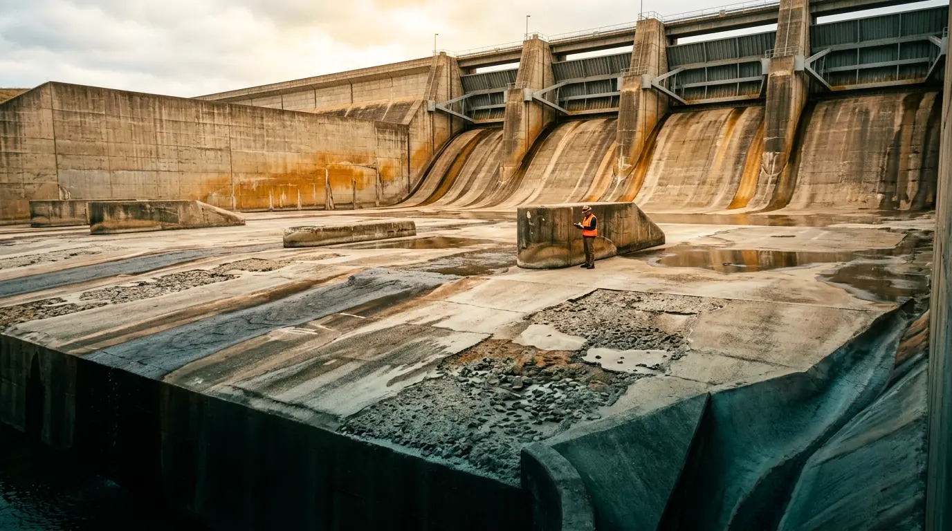
Inspection Protocol
Stilling basins should be dewatered and inspected annually during the non-monsoon season, ideally as part of a broader QA/QC programme that covers all dam concrete elements. The inspection should document:
- Erosion depths at grid points (typically 2 x 2 metre grid)
- Condition of all joints and waterstops
- Damage to baffle blocks and end sills (dimensional measurements)
- Cavitation patterns and surface condition
- Condition of drainage system
- Displacement or settlement of slab panels
Repair Materials
The choice of repair material depends on the depth and extent of damage.
| Damage Depth | Repair Method | Material |
|---|---|---|
| Less than 25 mm | Surface coating | Epoxy or polyurethane coating |
| 25-75 mm | Polymer-modified mortar | Styrene-butadiene or acrylic modified cement mortar |
| 75-200 mm | Conventional concrete patch | High-strength concrete (50 MPa+) with bonding agent |
| 200-500 mm | Formed concrete repair | Silica fume concrete with steel fibres |
| Greater than 500 mm | Full-depth replacement | Remove and replace with dowelled new concrete |
All repairs must maintain the smooth surface profile required to prevent cavitation. A poorly executed repair that leaves a protruding edge will erode faster than the original damage. Selecting the right concrete repair materials is as critical as the original construction.
Protective Surface Treatments
For stilling basins experiencing severe and recurring erosion, protective surface treatments can extend the time between repairs:
- Epoxy mortar overlays. 10 to 20 mm thick, providing excellent abrasion resistance. However, bond durability under thermal cycling and sustained water exposure is a concern.
- Steel fibre-reinforced concrete overlays. 75 to 150 mm thick, bonded with epoxy to the parent concrete. More durable than epoxy alone but more expensive.
- Polyurea coatings. Flexible, impact-resistant coatings that can absorb some of the cavitation energy. Effective for moderate conditions but can delaminate under severe hydraulic loading.
- Steel plate lining. For the most severe conditions, stainless steel plates anchored to the concrete surface provide the ultimate protection. This is common practice on high-head spillway chutes but less common in stilling basins due to the complex geometry.
ICOLD Bulletin 141 provides comprehensive guidance on the concrete rehabilitation of dams, including stilling basin repair strategies and material selection.
Case Considerations from Practice
Experience across multiple hydroelectric projects reveals common patterns in stilling basin concrete performance.
Sediment-Heavy Rivers
On hydropower dam projects in the Himalayan region, rivers carry exceptionally high sediment loads during monsoon floods. The combination of high velocity and high sediment concentration produces abrasion rates of 10 to 30 mm per flood season in unprotected stilling basins. The most effective countermeasure is high-strength (50 MPa+), silica fume concrete with hard aggregate, combined with a geometry that minimises sediment accumulation in the basin.
High-Head Spillways
For spillways with heads exceeding 50 metres, the risk of cavitation in the stilling basin increases dramatically. Flow velocities at the basin floor can exceed 30 m/s, and surface tolerances must be tightened to plus or minus 2 mm. Aerator slots in the spillway chute can reduce cavitation intensity by introducing air into the flow boundary layer, but they do not eliminate it.
Flood Debris Impact
Large Himalayan rivers transport boulders during extreme flood events. A 500 kg boulder travelling at 10 m/s carries kinetic energy of 25,000 joules upon impact with the basin floor. No concrete can resist repeated impacts of this magnitude without damage. Design strategies include sacrificial concrete layers (removable precast blocks), steel armour plates on impact zones, and deepened basin floors that allow sediment to accumulate and cushion impacts.
Conclusion
Stilling basin concrete operates in the most extreme hydraulic environment found in any dam project. The combination of impact, abrasion, cavitation, and dynamic loading demands a concrete technology approach that is fundamentally different from mass concrete or structural concrete design.
The core principles are clear: use hard, dense aggregate with low Los Angeles abrasion values; specify low w/c ratios (0.35 to 0.40) with silica fume; insist on surface tolerances that minimise cavitation inception; cure thoroughly; inspect annually; and repair promptly before minor erosion becomes major structural damage. When concrete deterioration warning signs appear in a stilling basin, immediate assessment is essential.
A stilling basin designed and built with these principles will still require periodic maintenance. But the difference between a well-designed stilling basin and a poorly designed one is not whether repairs will be needed. It is whether the repairs are manageable maintenance items performed during planned shutdowns or emergency interventions that take the dam offline for months. This is precisely the kind of durability and service-life engineering that determines whether a dam delivers reliable power for decades or becomes a recurring cost centre.