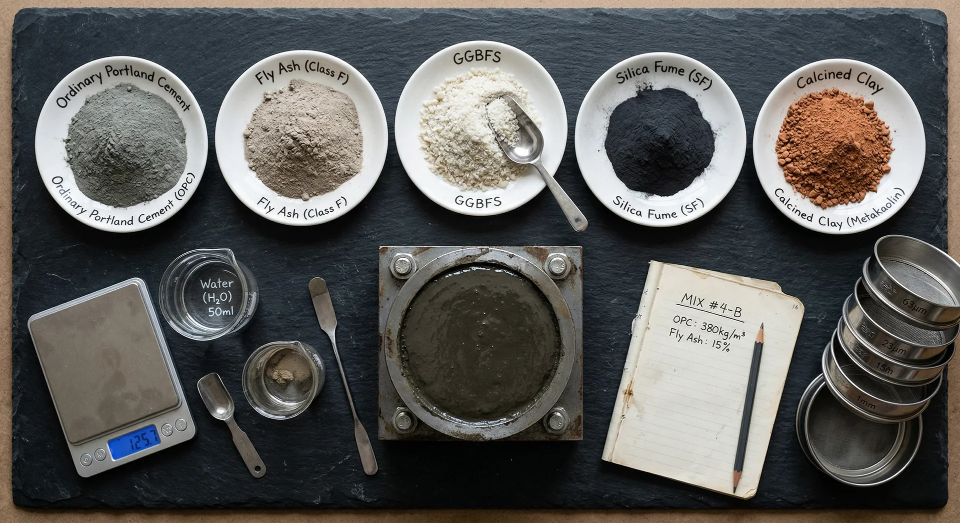
Fly ash belongs in most spillway wearing-layer concrete: at 10-15% of cementitious content it barely affects abrasion resistance, and a ternary blend of silica fume plus 15-25% Class F fly ash delivers 85-95% of binary abrasion performance while adding the alkali-aggregate reaction protection that reactive Himalayan aggregates demand, verified through ASTM C1138 and ASTM C1567 testing.
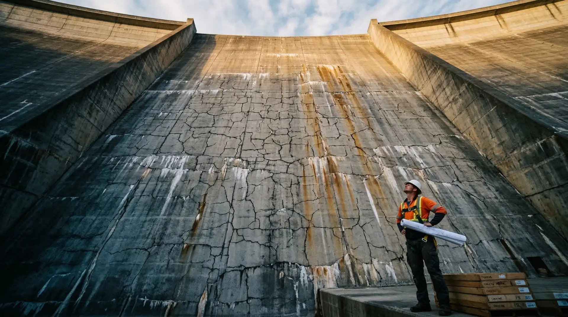
The spillway wearing layer is the most exposed and abused concrete surface on any dam. It must withstand decades of high-velocity water carrying sand, gravel, and silt at speeds that can exceed 30 m/s during flood discharge. Unlike structural mass concrete buried within the dam body, the wearing layer has no margin for underperformance. It is either hard enough to resist erosion, or it is not.
This makes the question of supplementary cementitious materials (SCMs) in the wearing layer mix a high-stakes decision. Silica fume has an established track record of improving abrasion resistance. But fly ash, the most widely available and cost-effective SCM in South Asia, carries a reputation problem: the perception that it weakens the concrete surface. For projects where alkali-aggregate reaction (AAR) is a known risk, this creates a genuine engineering dilemma. Excluding fly ash may improve abrasion resistance but leave the concrete vulnerable to expansive reactions that cause far more damage over a 50 to 100-year service life.
This technical brief examines the research evidence, field data, and current standards to answer a practical question: should fly ash be included in spillway wearing layer concrete, and if so, how much?
The Three Erosion Mechanisms: A Quick Recap
Before discussing SCM strategies, it is worth recalling the three distinct mechanisms that damage spillway surfaces. Each one responds differently to concrete composition.
Abrasion occurs when sediment-laden water grinds against the concrete surface. It is the dominant erosion mechanism on most spillways, especially those in rivers carrying significant bed load. Resistance depends primarily on aggregate hardness, paste density, and compressive strength.
Cavitation occurs at high velocities (typically above 12 m/s) when water pressure drops below vapour pressure, forming and collapsing bubbles that pit the surface. Cavitation resistance depends more on tensile strength and surface finish than on SCM content.
Chemical dissolution is a slower process where soft water or acidic runoff gradually leaches calcium from the cement paste. SCMs that reduce permeability generally improve dissolution resistance.
For a detailed treatment of all three mechanisms, see our companion article on spillway concrete abrasion and cavitation resistance. This article focuses specifically on abrasion resistance and how fly ash affects it.
What does the ASTM C1138 abrasion test actually tell us?
ASTM C1138, “Standard Test Method for Abrasion Resistance of Concrete (Underwater Method),” is the primary laboratory test for evaluating spillway concrete. Understanding its limitations is essential for interpreting the research literature.
The test protocol places a concrete disc (approximately 300 mm diameter, 100 mm thick) in a cylindrical container with water and steel grinding balls. An agitating paddle circulates the balls across the concrete surface for 72 hours. Mass loss is measured at 12-hour intervals.
Key points engineers should understand:
- No pass/fail benchmark. ASTM C1138 is purely comparative. There is no threshold value that defines “acceptable” abrasion resistance. Results are meaningful only when comparing multiple mixes tested under identical conditions.
- Typical ranges. Conventional concrete (30 to 40 MPa) typically shows 5 to 10% mass loss after 72 hours. High-performance concrete with silica fume (60 to 70 MPa) typically shows 2 to 5% mass loss. These are general ranges, not specification limits.
- Aggregate dominates. Once the paste wears away, aggregate hardness becomes the controlling factor. Hard igneous aggregates (granite, basalt) consistently outperform softer sedimentary aggregates regardless of SCM content.
- Test variability. Coefficient of variation between laboratories can exceed 15%, making small differences between mixes statistically insignificant. A 1 to 2% difference in mass loss between two mixes tested in different labs is essentially noise.
The practical implication: when evaluating fly ash versus non-fly-ash mixes, only test them side by side in the same laboratory, on the same equipment, using identical aggregates. Comparing published values across different studies is unreliable.
Fly Ash and Abrasion Resistance: The Evidence
The research record on fly ash and abrasion spans four decades. The findings are more consistent than the industry debate suggests.
The Strength Effect, Not a Fly Ash Penalty
The most important finding across the research is that abrasion resistance is governed primarily by compressive strength and water-cementitious ratio, not by fly ash content as such.
Yen et al. (2007) tested high-strength concrete (28-day strength of roughly 40 to 80 MPa) with Class F fly ash at 15%, 20%, 25%, and 30% replacement under ASTM C1138. Abrasion-erosion resistance was comparable to the control up to about 15% replacement and declined measurably beyond it, with compressive strength and water-cementitious ratio the dominant controls: higher-strength, lower-w/cm mixes resisted abrasion better at every replacement level.
The practical conclusion is that keeping fly ash at or below about 15% in the wearing layer, and designing to an adequate strength grade, avoids any meaningful abrasion penalty: at these dosages the pozzolanic densification of the paste offsets the slower strength gain. Higher replacement levels belong in the structural concrete beneath the wearing layer, where abrasion is not the governing concern.
Foundational Work by Liu (1981)
Liu’s early research at the U.S. Army Engineer Waterways Experiment Station established the baseline understanding that concrete compressive strength and aggregate hardness are the two dominant factors in abrasion resistance. His work showed that for a given aggregate, raising compressive strength markedly reduces abrasion losses. This finding is critical because it means that if fly ash is used at a level that does not compromise strength (or if the mix is designed to a higher grade to compensate), the abrasion penalty can be effectively neutralized.
Why Low Dosages Can Help
At low replacement levels, fly ash can improve abrasion resistance rather than reduce it. Through pozzolanic reaction it refines the pore structure and densifies the interfacial transition zone between paste and aggregate, producing a harder, less permeable surface. This effect is most useful at dosages around 10 to 15%, where the densification benefit is not yet offset by the slower strength gain that accompanies higher replacement levels.
The Early-Age Concern
The legitimate concern with fly ash in wearing layer concrete is early-age strength development. Fly ash concrete gains strength more slowly than ordinary Portland cement (OPC) concrete, particularly in the first 7 to 14 days. If the spillway must be placed in service before the fly ash has fully reacted (for example, due to monsoon scheduling), the surface may be more vulnerable during its initial exposure.
This concern is manageable through two approaches:
- Design for 56 or 90-day strength rather than 28-day, giving the fly ash time to develop its full contribution.
- Keep fly ash below 15% in the wearing layer, even if higher dosages are used in the structural mass concrete beneath it.
Silica Fume: The Proven Performer
Silica fume’s role in improving abrasion resistance is well established and not controversial. The mechanism is straightforward: its extreme fineness (average particle size of 0.1 to 0.2 microns, roughly 100 times finer than cement) fills micropores in the paste, reacts with calcium hydroxide to form additional C-S-H gel, and dramatically reduces permeability.
The Kinzua Dam Case Study
The landmark study by Holland et al. (1986) at Kinzua Dam in Pennsylvania demonstrated silica fume’s potential for spillway repair. The silica fume high-performance concrete used in the stilling-basin repair showed markedly lower abrasion-erosion loss than the conventional concrete it replaced. This work, referenced in ACI 210R-93, “Erosion of Concrete in Hydraulic Structures,” became the basis for widespread adoption of silica fume in spillway concrete.
The Strength-and-Silica-Fume Relationship
Across the published hydraulic-concrete literature, two findings recur for wearing layer mixes: silica fume substantially improves abrasion resistance, and higher compressive strength provides additional benefit. Moving from a conventional M40 mix to a silica-fume high-performance mix at M60 to M70 typically reduces ASTM C1138 mass loss by roughly half, combining the pore-refining effect of silica fume with the harder, denser paste matrix that higher strength provides.
ACI Recommendation
ACI 210R-93 recommends silica fume concrete with the lowest practical water-cementitious ratio and hard, abrasion-resistant aggregate for hydraulic structures subject to abrasion-erosion. In wearing layer practice, this typically translates to silica fume at 8 to 12% of cementitious content and a water-cementitious ratio at or below 0.35.
Binary vs. Ternary Blends: The Real Comparison
The debate about fly ash in spillway concrete is often framed as “fly ash vs. no fly ash.” The more useful comparison is between binary blends (cement plus silica fume) and ternary blends (cement plus silica fume plus fly ash). This reframing changes the analysis significantly.
Binary Blends: Maximum Abrasion, No AAR Protection
A binary blend of OPC plus 8 to 10% silica fume, designed to M50 or M70 grade, delivers the highest abrasion resistance achievable with SCMs. It is the right choice when:
- Aggregates are confirmed non-reactive through ASTM C1260 and ASTM C1293 testing
- Alkali loading from cement is low (Na2Oeq below 0.60%)
- The sole priority is maximizing surface hardness
The limitation is that silica fume alone, at the 8 to 10% dosages used in wearing layer mixes, provides limited protection against AAR. While silica fume does consume some alkalis, its effectiveness against slowly reactive aggregates over long timeframes is not reliable.
Ternary Blends: Near-Equal Abrasion Plus Multi-Threat Protection
Ternary blends add 15 to 25% Class F fly ash to the silica fume system. The research data on this combination is compelling.
Across the published research on ternary hydraulic-concrete systems, a consistent pattern emerges. A blend of cement plus roughly 7 to 8% silica fume plus 15 to 20% Class F fly ash achieves abrasion resistance close to that of a binary silica fume mix, typically within about 10% at 28 days, with the gap narrowing at later ages as the fly ash pozzolanic reaction continues. The same ternary systems consistently show better resistance to chloride penetration and sulfate attack than binary mixes, and provide the alkali-silica reaction protection that silica fume alone cannot reliably deliver.
The comparison in practical terms:
| Property | Binary (OPC + SF) | Ternary (OPC + SF + FA) |
|---|---|---|
| 28-day abrasion resistance | Excellent | Very good (85 to 95% of binary) |
| 90-day abrasion resistance | Excellent | Excellent (90 to 98% of binary) |
| AAR protection | Limited | Strong (with 15%+ Class F FA) |
| Workability | Moderate (SF increases cohesion) | Good (FA improves flow) |
| Heat of hydration | Moderate | Lower (FA reduces peak temperature) |
| Plastic shrinkage risk | Higher | Lower |
| Cost | Higher (SF is expensive) | Lower (FA offsets some SF cost) |
For most hydroelectric projects, the ternary blend delivers the better risk-adjusted outcome.
Why does alkali-aggregate reaction change the fly ash decision?
The discussion above treats abrasion and AAR as separate concerns. In practice, for many hydroelectric projects in South and Southeast Asia, they are deeply connected. This is because the same aggregates used in the spillway wearing layer are typically sourced from local river deposits or quarries, and many of these aggregates are reactive.
Himalayan Aggregates and ASR Reactivity
The geological reality of the Himalayan region is that many common aggregate sources contain reactive silica minerals: strained quartz, chert, chalcedony, volcanic glass, and phyllosilicates. Well-documented cases of ASR damage in South Asian dams include:
- Tarbela Dam (Pakistan): Mild ASR from slowly reactive aggregates, the first reported ASR case in Pakistan
- Warsak Dam (Pakistan): Aggressive ASR requiring major repairs and a partial shutdown
- Hirakud Dam (India): ASR diagnosed roughly three decades after construction
FHWA (Federal Highway Administration) guidance and the AASHTO PP65 prescriptive approach set the required fly ash level by the ash’s calcium content and the aggregate’s reactivity: low-calcium Class F fly ash can be effective at lower dosages, moderate-calcium ash typically requires 25 to 35%, and highly reactive aggregates or long-service-life critical structures need more. This works through fly ash’s dual mechanism of alkali binding and pore solution chemistry modification.
Why Silica Fume Alone May Not Be Enough
ACI PRC-201.2-16 (Guide to Durable Concrete) and ASTM C1778 provide prescriptive levels of SCMs required to prevent ASR based on aggregate reactivity class and exposure conditions. For moderately to highly reactive aggregates in moist environments (which describes virtually every spillway), the guidance recommends:
- Silica fume alone: 10 to 15% (higher than typically used for wearing layer, and this much SF creates workability problems)
- Class F fly ash alone: 25 to 40%
- Ternary (SF + FA): 7 to 8% SF plus 15 to 25% FA
The ternary approach achieves adequate ASR prevention at SCM levels that remain compatible with abrasion resistance requirements.
The 10 to 30-Year Latency Problem
ASR is not an immediate failure. Slowly reactive aggregates may take 10 to 30 years to develop visible damage. A spillway that performs beautifully for its first decade may begin showing map cracking, gel exudation, and expansion-related structural distress in its second or third decade. By that point, the cost of repair is orders of magnitude higher than the cost of proper SCM selection during original construction.
This latency means that the absence of ASR in young concrete is not evidence that the aggregates are non-reactive. It means the reaction has not yet had enough time, moisture exposure, and alkali accumulation to manifest. For a spillway designed for 75 to 100 years of service, a mix that sacrifices AAR protection for marginally better abrasion resistance is a poor trade.
Recommended Specifications for Spillway Wearing Layer
Based on the evidence reviewed above, the following specifications represent current best practice for spillway wearing layer concrete. Three options are presented to match different aggregate reactivity scenarios.
Option 1: Binary Blend (Non-Reactive Aggregates Confirmed)
Use only when aggregate non-reactivity is confirmed through both ASTM C1260 (14-day mortar bar) and ASTM C1293 (1-year concrete prism) testing with project-specific materials.
| Parameter | Specification |
|---|---|
| Grade | M60 to M70 |
| w/cm ratio | 0.32 to 0.35 (maximum) |
| Cement content | 380 to 420 kg/m3 total cementitious |
| Silica fume | 8 to 10% of total cementitious |
| Fly ash | None |
| Coarse aggregate | Hard igneous (granite, basalt); Los Angeles abrasion less than 25% |
| Fine aggregate | Manufactured sand preferred; natural sand fineness modulus (FM) 2.6 to 3.0 |
| Curing | 14 days minimum wet curing; 28 days preferred |
| Testing | ASTM C1138 comparative test of all candidate mixes |
Option 2: Ternary Blend, Conservative (Moderate Reactivity Risk)
Appropriate when ASTM C1260 results show borderline expansion (0.10 to 0.20% at 14 days) or when aggregate testing is incomplete.
| Parameter | Specification |
|---|---|
| Grade | M55 to M65 |
| w/cm ratio | 0.33 to 0.36 (maximum) |
| Total cementitious | 400 to 440 kg/m3 |
| Silica fume | 7 to 8% of total cementitious |
| Fly ash (Class F) | 15% of total cementitious |
| Total SCM | 22 to 23% |
| Coarse aggregate | Hard igneous; LA abrasion less than 25% |
| Fine aggregate | FM 2.6 to 3.0 |
| Strength age | 56-day characteristic strength |
| Curing | 14 days minimum wet curing |
| Testing | ASTM C1138 + ASTM C1567 (mortar bar with proposed SCMs) |
Option 3: Ternary Blend, Full AAR Protection (Reactive Aggregates)
Required when aggregates are confirmed reactive (ASTM C1260 expansion exceeding 0.20%) or when aggregate sources are variable and reactivity cannot be guaranteed batch to batch.
| Parameter | Specification |
|---|---|
| Grade | M50 to M60 |
| w/cm ratio | 0.34 to 0.37 (maximum) |
| Total cementitious | 420 to 460 kg/m3 |
| Silica fume | 7 to 8% of total cementitious |
| Fly ash (Class F) | 25% of total cementitious |
| Total SCM | 32 to 33% |
| Coarse aggregate | Best available; LA abrasion less than 30% |
| Fine aggregate | FM 2.6 to 3.0 |
| Strength age | 90-day characteristic strength |
| Curing | 21 days minimum wet curing; extended moist curing strongly recommended |
| Testing | ASTM C1138 + ASTM C1567 + ASTM C1293 (with proposed SCMs) |
Critical Note on Fly Ash Quality
All three options assume low-calcium Class F fly ash meeting ASTM C618, with project limits tightened for wearing-layer use to loss on ignition (LOI) below 3%, fineness (retained on 45-micron sieve) below 25%, and CaO content below 10%, stricter than the ASTM C618 Class F maxima of 6% LOI and 34% retained. Indian fly ash quality varies significantly between sources. Every batch should be tested before use. High-calcium (Class C) fly ash from lignite combustion is NOT suitable for AAR prevention and should not be substituted without re-evaluation of the entire mix design.
The Practical Decision Framework
For engineers and project managers making this decision, the flowchart is straightforward.
Step 1: Characterize the aggregates. Conduct ASTM C1260 and ASTM C1293 testing on all proposed aggregate sources. Do not rely solely on petrographic examination, which can miss slowly reactive minerals. If the project timeline does not allow for the 12-month ASTM C1293 test, use ASTM C1260 as a screening tool and default to the conservative ternary approach.
Step 2: Assess the risk tolerance. Consider the service life (typically 75 to 100 years for a dam spillway), the difficulty and cost of future repairs, and the consequence of AAR-related deterioration. For major hydroelectric projects where spillway failure would compromise the dam safety programme, the cost of extra fly ash is trivial relative to the risk.
Step 3: Select the blend.
- Aggregates confirmed non-reactive (both ASTM C1260 and C1293 pass): Binary SF blend is optimal for maximum abrasion resistance.
- Aggregates reactive, borderline, or untested: Ternary blend with 15 to 25% Class F fly ash plus 7 to 8% silica fume. The exact fly ash percentage should be determined through ASTM C1567 testing with the proposed SCM combination.
- Aggregates highly reactive or sources variable: Ternary blend at the upper end (25% FA) with mandatory ASTM C1293 confirmation testing of the proposed mix.
Step 4: Validate with ASTM C1138. Regardless of which option is selected, conduct ASTM C1138 comparative testing on at least three candidate mixes using the actual project aggregates and cementitious materials. This test is the final check that the selected mix meets abrasion performance expectations relative to the other options.
Wearing Layer vs. Body Concrete
The specifications above apply to the top 150 to 300 mm wearing layer of the spillway chute. The structural body concrete beneath can use higher fly ash dosages (25 to 40%) for thermal control and economy, since it is not directly exposed to abrasion. This two-layer approach is standard practice on major spillway projects and allows optimization of each layer for its specific exposure conditions. See our guide on SCM strategies for dam concrete for full details on body concrete mix design.
What do South Asian hydroelectric projects teach about fly ash?
The experience of PCCI’s leadership across six landmark hydroelectric projects, totalling over 4,000 MW, has provided direct insight into the fly ash question in the context of Himalayan and sub-Himalayan geology.
At the Tala HEP, the wearing-layer approach combined silica fume with high strength grades, with aggregate sources from Bhutanese river deposits characterized through comprehensive testing to establish the appropriate mix design strategy.
At the Karchham Wangtoo HEP in Himachal Pradesh, mix designs spanning concrete, shotcrete, and grout were developed with careful attention to the locally available aggregates and their long-term durability characteristics.
The consistent lesson across these projects is that the decision about fly ash in the wearing layer cannot be made in isolation. It must be integrated with a comprehensive understanding of aggregate reactivity, exposure conditions, required service life, and the overall SCM strategy for the project.
Conclusion
The question “Should fly ash be used in the spillway wearing layer?” does not have a universal answer. The evidence supports three clear conclusions:
First, fly ash at 10 to 15% of cementitious content does not significantly impair abrasion resistance. The historical reluctance to use any fly ash in wearing layers is not supported by the current research base.
Second, for projects where aggregate reactivity is a concern (and in the Himalayan region, it almost always should be), excluding fly ash from the wearing layer creates a long-term durability risk that far outweighs the marginal abrasion benefit of a pure silica fume system.
Third, the optimal approach for most hydroelectric spillways is a ternary blend combining silica fume (for abrasion resistance and impermeability) with Class F fly ash (for AAR protection and workability), at dosages calibrated to the specific aggregate reactivity and verified through both ASTM C1138 and ASTM C1567/C1293 testing.
The wearing layer is too important and too expensive to repair for mix design decisions to be based on convention rather than evidence. Test the aggregates. Test the mixes. Let the data drive the decision.
If your project requires technical guidance on spillway concrete mix design, aggregate reactivity assessment, or SCM optimization, contact our team to discuss your specific requirements.