When non-conforming concrete is found on a hydropower dam, the decision is among five standards-based outcomes (accept-as-is, accept-with-restrictions, repair-and-accept, reject-and-replace, or investigate-further) applied across six recurring categories of non-conformance. Which outcome is correct depends on the specific structural element, the specific deficiency, the standards-based acceptance criterion, and the consequence chain. The five outcomes are bounded by IS 456:2000, ACI 318-25, and ACI CODE-562-25; the choice among them is engineering judgment.
Every hydropower dam construction programme produces non-conforming concrete at some point. A cube fails at 28 days. A dimensional check shows the wall is 12 mm off the design. Honeycombing appears after form stripping. Ultrasonic pulse velocity readings on a lift show velocities outside the acceptance band. The cement supplier sends a batch with alkali content 0.12 percentage points above the previous lot. Each is a non-conformance. None of them is automatically a structural failure. None of them is automatically a candidate for repair or rejection. The decision among the five possible responses is the engineering question.
The decision is not whether to act. The decision is which of the five responses applies: accept as is, accept with restrictions, repair and accept, reject and replace, or investigate further. The five outcomes are bounded by standards: IS 456:2000 Clause 17 on the Indian side, ACI 318-25 Section 26.12 on the international side (the framework is unchanged from ACI 318-19), ACI CODE-562-25 on assessment, repair, and rehabilitation of existing concrete structures, and the project’s contract specification. The decision among them is bounded by engineering judgment applied to the specific industry context, the specific structural element, the specific deficiency, and the specific consequence chain.
This is the practitioner decision framework, anchored on those standards and refined across more than 4,000 MW of hydroelectric concrete placement. It covers six categories of non-conformance and the five decision outcomes that apply to each. The owner’s engineer’s job is to walk the framework deliberately, document the reasoning, and ensure the disposition is the one the structure actually warrants, not the one schedule pressure wants.
What are the five possible decision outcomes?
Every non-conformance disposition resolves to one of five outcomes:
A. Accept-as-is. The non-conformance is within tolerance, has no structural impact, no durability impact, and no operational impact. The concrete stays in place with no modification and no restriction. Documentation is required; physical action is not.
B. Accept-with-restrictions. The non-conformance is bounded but real. The concrete stays in place without physical modification, but with documented restrictions: reduced design load, additional monitoring cadence, supplementary NDT campaign, restrictions on adjacent construction, or modified service-life expectation. The structure remains serviceable by reducing demand to match the reduced capacity.
C. Repair-and-accept. The non-conformance is correctable. After a specified repair, the concrete meets the design intent. Repair is engineered, executed, verified, and documented. The structure carries the original design load post-repair.
D. Reject-and-replace. The non-conformance is not correctable, or correction would cost more than removal and replacement. The non-conforming concrete is removed and replaced with conforming concrete. This outcome is rare on dam projects because mass concrete demolition is expensive, but when it is the right answer it is usually obvious.
E. Investigate-further. The information available does not support a confident decision. Additional testing (cores, NDT, petrographic analysis, load test) or analysis (structural reanalysis, finite-element modelling) is required before the disposition is decided. After investigation, the case returns to one of A, B, C, or D.
A sixth implicit outcome, Halt-and-escalate, is invoked from E when the situation is critical: the cause is not yet known, proceeding could compound the defect, or the structural impact is potentially severe. Halt is escalated to the project owner with a written report within 24 hours and a recommendation. Halts are rare but must be visibly on the table.
What are the six categories of non-conforming concrete on a dam?
Category 1: Compressive strength shortfall
Typical trigger. A 28-day cube test result is below the acceptance criterion. Per IS 456:2000 Clause 16, mean of four consecutive samples must be at least fck + 0.825σ, and each individual sample at least fck − 3 N/mm² for M15 and above. Per ACI 318-19 Section 26.12.3, average of three consecutive strength tests must equal or exceed f’c, and no single test more than 3.5 MPa below f’c (for f’c ≤ 35 MPa).
Standards-based decision path:
-
Verify the test. Confirm cube preparation per IS 516 or ASTM C31/C31M (Practice for Making and Curing Concrete Test Specimens in the Field), cure at 27°C ± 2°C (IS) or 23°C ± 2°C (ASTM), test per IS 516 / ASTM C39/C39M (Compressive Strength of Cylindrical Concrete Specimens). A miscalibrated testing machine or a cube cured at the wrong temperature produces apparent failures that are not concrete failures.
-
Trend check. Review 7-day, 56-day, and 90-day cubes from the same batch. Mass concrete continues to gain strength well beyond 28 days; an early-age low cube may resolve at later ages.
-
In-place strength assessment. If the test is valid and the trend is concerning, perform core testing per IS 456 Clause 17.4 or ACI 318 Section 26.12.6.1. Minimum 3 cores per area of concern, per ASTM C42/C42M (Standard Test Method for Obtaining and Testing Drilled Cores and Sawed Beams of Concrete), with minimum diameter equal to 3× the maximum aggregate size and absolute minimum 75 mm.
-
Apply the core acceptance criterion. Average of 3 cores ≥ 85% of fck/f’c, AND no individual core < 75%. Both IS 456 and ACI 318 use the same 0.85/0.75 numerical framework.
-
Decide:
- Cores pass: Accept-as-is.
- Cores fail marginally (e.g., 80-85% average with no individual below 75%): consider Accept-with-restrictions with structural reanalysis at reduced strength.
- Cores fail substantially (average below 75%): Investigate-further via structural reanalysis or load test per ACI CODE-437.2-22 (Load Testing of Concrete Structures); evaluate Repair-and-accept via strengthening per ACI 562 or Reject-and-replace for catastrophic shortfall.
Common errors.
- Reading the cube failure as a structural failure rather than as a quality-control trigger for investigation.
- Skipping the verification step and going directly to coring.
- Coring only one or two locations instead of the minimum three per area of concern.
- Accepting the contractor’s lab cores without independent supervision of the coring location selection.
- Decision made by contractor’s quality manager without owner’s engineer concurrence.
Category 2: Dimensional deviation
Typical trigger. A formwork stripping survey shows the structural element is outside the contract dimensional tolerance: a wall is thicker or thinner, a gallery is offset from the centerline, an embedded item is misplaced, a contraction joint is at the wrong elevation.
Standards-based decision path:
-
Quantify the deviation. Measure the deviation precisely, document with photographs and survey data. Map the deviation against the structural drawings.
-
Assess structural impact. Does the deviation reduce the structural capacity below the design demand? For a wall thickness deviation, the moment and shear capacity scale roughly with thickness; a 5 percent reduction needs a 5 percent capacity check. For an embedded item misplacement, the cover and the structural load path may be affected.
-
Assess functional impact. Does the deviation affect the structure’s function? A misaligned gallery may still serve its drainage function; a misaligned penstock embedment may not.
-
Apply the contract tolerance. Contract specifications typically allow tolerances of ±10 mm to ±25 mm for mass concrete elements per ACI 117 or equivalent. If within tolerance, Accept-as-is. If outside tolerance, proceed to outcome decision.
-
Decide:
- Outside tolerance but no structural or functional impact: Accept-as-is with documented deviation in the as-built record.
- Outside tolerance with bounded impact: Accept-with-restrictions (e.g., revised load assumption, additional reinforcement in subsequent lift) or Repair-and-accept (e.g., shotcrete buildup, chipping back to design line).
- Outside tolerance with severe impact: Reject-and-replace (uncommon on mass concrete dams due to demolition cost, but applicable on smaller members).
- Uncertain impact: Investigate-further with structural reanalysis.
Common errors.
- Comparing measured dimensions to design drawings rather than to as-built tolerances.
- Failing to update subsequent lifts’ formwork for the cumulative dimensional drift.
- Missing the embedded item misplacement until the subsequent lift conceals it.
Category 3: Surface defect
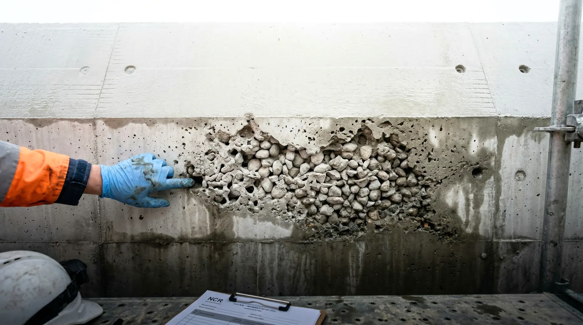
Typical trigger. Form stripping reveals honeycombing, segregation, exposed reinforcement, surface scaling, or finish defects, of which honeycombing in dam concrete is the most frequently encountered category on hydropower projects.
Standards-based decision path:
-
Determine depth. Surface defects can be cosmetic (surface only, less than 25 mm deep) or structural (penetrating to depth, exposing reinforcement, compromising cover). NDT methods (UPV, impact-echo) or selective core extraction confirm depth.
-
Assess cover and reinforcement. If reinforcement is exposed, the design cover for that exposure class (IS 456 Table 16, or ACI 318 Section 20.6) is breached. Cover loss accelerates corrosion onset.
-
Assess water-bearing surface. For dam upstream face, intake, spillway, hydraulic galleries, surface defects accelerate hydraulic deterioration and seepage.
-
Decide:
- Cosmetic depth, no cover loss, no functional impact: Accept-as-is.
- Cosmetic to shallow depth with cover marginally affected: Accept-with-restrictions (additional surface treatment in service, monitoring).
- Penetrating to depth or exposing reinforcement: Repair-and-accept with surface mortar repair, epoxy injection, or section build-up per ACI 562 / ACI 546.
- Honeycombing extending through structural depth with exposed reinforcement on a critical element: Investigate-further via core extraction and NDT, then likely Repair-and-accept with structural strengthening, or in rare severe cases Reject-and-replace that section.
Common errors.
- Assuming surface defects are surface-only without NDT depth confirmation.
- Surface patching with non-shrink mortar over honeycombing that extends 200 mm into the section.
- Skipping cover restoration for exposed reinforcement, leaving a corrosion-initiation site.
Category 4: Cracking
Typical trigger. Cracks observed during construction or shortly after form stripping. Causes range across plastic shrinkage, plastic settlement, thermal contraction, drying shrinkage, restraint cracking, AAR, structural overload, and construction defects (cold joint, formwork failure). The diagnosis workflow for cracks on dam structures starts with cause attribution before any disposition decision is made.
Standards-based decision path:
-
Diagnose the crack per the 5-step workflow: observe, classify, diagnose, assess severity (structural, durability, watertightness), decide response.
-
Apply IS 456 / fib crack width limits for the structural element’s exposure class:
- Mild exposure: ≤ 0.3 mm
- Moderate exposure: ≤ 0.2 mm
- Severe / Very Severe / Extreme: ≤ 0.1 mm
-
Decide per the severity assessment:
- Within width limit, surface only, no seepage path: Accept-as-is with crack register entry.
- Within width limit but suspected active or in critical location: Accept-with-restrictions with monitoring (DEMEC studs, dial gauges, vibrating-wire crack meters).
- Exceeds width limit but cause known and bounded: Repair-and-accept (epoxy injection for structural, polyurethane injection for seepage, surface seal for combined cosmetic and durability concerns).
- Suspected AAR, structural cause, or extensive map cracking: Investigate-further (NDT, cores, petrographic analysis, structural reanalysis).
- Catastrophic structural cracking under load: Reject-and-replace that section; rare but applicable.
Common errors.
- Single-cause diagnosis without considering combined mechanisms.
- Sealing the crack before documenting it (destroys diagnostic evidence).
- Treating all cracks at the same severity regardless of structural element criticality.
Category 5: NDT-flagged anomaly
Typical trigger. Ultrasonic pulse velocity (UPV) per IS 516 Part 5/Sec 1:2018 (Non-destructive Testing of Concrete: Ultrasonic Pulse Velocity), which superseded the withdrawn IS 13311 Part 1:1992, rebound hammer per IS 516 Part 5/Sec 4:2020 (Non-destructive Testing of Concrete: Rebound Hammer Test), which superseded the withdrawn IS 13311 Part 2:1992, impact-echo, half-cell potential, or GPR identifies an anomaly: UPV velocity outside acceptance band, rebound number scatter, impact-echo signal indicating void or delamination, half-cell potential indicating corrosion onset.
Standards-based decision path:
-
Verify the NDT result. NDT methods have method-specific calibration requirements. UPV velocity depends on coupling, transducer alignment, concrete moisture, and aggregate type. Rebound is surface-sensitive. Verify the equipment calibration and the operator technique before accepting the result as indicating a real defect.
-
Correlate with cores. NDT methods alone do not provide acceptance-criterion strength. Where strength is the concern, NDT identifies suspect zones; cores per ASTM C42 confirm the actual strength.
-
Assess the implied defect. Per IS 516 Part 5/Sec 1:2018 Table 1 (Clause 2.5.2), UPV velocity by cross probing grades concrete quality as Excellent above 4.40 km/s, Good 3.75 to 4.40 km/s, Doubtful 3.00 to 3.75 km/s, and Poor below 3.00 km/s. A “Doubtful” result triggers further investigation per the standard’s footnote. Impact-echo response indicating delamination at depth requires investigation.
-
Decide:
- NDT result within band, equipment calibrated, no other concern: Accept-as-is.
- NDT result marginal with corroborating cores within acceptance: Accept-as-is with documented NDT record.
- NDT result outside band, cores below acceptance: cascade to Category 1 (strength shortfall) or Category 3 (defect) decision path.
- NDT result inconclusive or contradictory: Investigate-further with additional NDT methods, core extraction, or visual investigation behind the suspect zone.
Common errors.
- Treating NDT result as definitive without independent verification (NDT is indicative, not definitive).
- Acting on UPV velocity without calibration certification on the specific concrete mix.
- Using rebound hammer on a carbonated or surface-treated face and reporting it as concrete quality.
Category 6: Material non-conformance
Typical trigger. Cement test certificate outside contract limits, aggregate gradation outside IS 383 envelope, fly-ash chemical composition outside ASTM C618 or IS 3812 limits, admixture-cement incompatibility identified during mix design trials, water source above ASTM C1602/C1602M (Standard Specification for Mixing Water Used in the Production of Hydraulic Cement Concrete) limits, or batching plant calibration outside IS 4926:2003 (Ready-Mixed Concrete: Code of Practice) tolerances (cement ±2%, aggregates and water ±3%).
Standards-based decision path:
-
Quarantine the material. Material identified as non-conforming is held pending decision, not placed in the structure.
-
Re-test. A single failing test certificate may be a sampling or laboratory issue. Re-test from a fresh sample of the same lot.
-
Assess the impact on concrete properties: heat of hydration, strength gain, durability, workability, set time. Calorimetry on the actual cement-SCM combination for thermal-control implications.
-
Decide:
- Re-test confirms within spec: Accept-as-is (the original test was an outlier).
- Re-test confirms non-conformance, but impact is bounded: Accept-with-restrictions (e.g., use only on non-critical elements, adjust mix design, increase fly-ash content to compensate).
- Re-test confirms non-conformance with significant impact: Reject the lot, return to supplier or dispose.
- Material already placed before the non-conformance was identified: cascade to Category 1 (strength) or Category 3 (defect) assessment of the placed concrete.
Common errors.
- Accepting the supplier’s certificate without independent verification (especially on cement alkali, fly-ash LOI).
- Failing to quarantine non-conforming material, allowing it to enter the batch plant feed.
- Treating each batch’s non-conformance as isolated rather than tracking source-level patterns.
The standards basis layered together
Six categories, five outcomes, and four governing standards. The framework looks complex on paper. In practice it is straightforward when applied consistently.
| Category | Primary code | Specific clause | Numerical threshold |
|---|---|---|---|
| Compressive strength shortfall | IS 456 / ACI 318 | IS Cl 17.4 / ACI §26.12.6.1 | Core avg ≥ 85% fck; individual ≥ 75% |
| Dimensional deviation | ACI 117 / contract spec | Various | Project-specific tolerance bands |
| Surface defect | ACI 562 / ACI 546 | Assessment + repair | Depth-based |
| Cracking | IS 456 / fib MC | IS Cl 35.3.2 Table 15 | 0.1/0.2/0.3 mm by exposure |
| NDT-flagged anomaly | IS 516 Part 5 (UPV, Rebound) / ACI 228.1R / ACI 228.2R | NDT method-specific | Indicative bands, requires correlation |
| Material non-conformance | IS 4926 / IS 383 / ASTM C150 / C618 / C1602 | Material-specific clauses | Material-property thresholds |
The framework’s value is its layered logic. Each category has a primary code that defines the acceptance criterion. Where the primary code does not give a numerical bound (e.g., cracking causal diagnosis), engineering judgment supplements it. Where the primary code’s numerical bound is exceeded, the framework escalates to one of the four investigative or corrective outcomes (B, C, D, E).
Authority and accountability
The decision authority on a hydropower dam project is the project owner, advised by the engineer of record (typically the design consultant) and the owner’s engineer (the independent technical authority).
The contractor identifies the non-conformance, documents it as a Non-Conformance Report (NCR), proposes a disposition, and executes the disposition once approved. The contractor does not have unilateral authority to dispose of non-conforming concrete.
The engineer of record provides the technical assessment: structural reanalysis, repair design, load test interpretation. On Indian projects, the engineer of record is typically the design consultant retained by the project owner.
The owner’s engineer provides independent review: verifying the contractor’s NCR, evaluating the proposed disposition, reviewing the engineer of record’s assessment, and signing off on the disposition with the project owner. On multilaterally funded projects (World Bank, ADB, JICA), the lender’s technical adviser may also review significant non-conformance decisions.
The project owner signs the final decision. The owner’s incentive is the structure’s 100-year service life, which is the correct incentive for non-conformance disposition.
This separation matters. The contractor has a structural incentive to minimise cost and schedule impact of non-conformance. The engineer of record has a structural incentive to be technically conservative. The owner’s engineer has a structural incentive to verify the truth. The project owner has the authority and the long-horizon interest. The decision benefits from this separation of incentive and authority. This is why PCCI’s Owner’s Engineer service operates independently of the contractor on hydropower dam programmes.
Common decision errors the owner’s engineer should flag
Error 1: Skipping the verification step. A failing cube test is treated as a strength failure without verifying the cube preparation, curing, and testing procedure. Many apparent strength shortfalls are testing-procedure failures.
Error 2: Coring at the wrong locations. Cores taken from convenient locations near form edges, away from the actual area of concern, do not represent the in-place strength. The owner’s engineer must approve coring locations before extraction.
Error 3: Decision under schedule pressure. A non-conformance identified late in a placement shift gets a quick “repair” disposition because halting the next lift is expensive. The right disposition is sometimes “halt and investigate,” and the right time to make that call is before the next lift, not after.
Error 4: Accepting verbal contractor commitments. A repair is “approved” verbally without documentation. The repair is executed without verification. The closeout is never written. Twenty years later, the NCR is open, the repair quality is unknown, and the structure carries an undocumented condition. Every NCR closes in writing.
Error 5: Treating all non-conformances equally. A 5 percent strength shortfall in a non-critical secondary works element is not the same problem as a 5 percent shortfall in the dam body upstream face. The decision framework explicitly factors in structural element criticality. The owner’s engineer’s job is to ensure the disposition matches the criticality.
Error 6: Confusing repair-and-accept with cosmetic patching. A surface patch over a structural defect is not a repair. Repair is engineered, executed against a specification, and verified. Patching is cosmetic. The two should not be confused in the NCR closeout.
Error 7: Investigate-further with no exit criteria. An NCR sits in “investigate” status for six months because no one defined what evidence would resolve the investigation. Investigation must have time-bounded exit criteria.
How the decision integrates into the project quality system
The decision framework is not a standalone exercise. It feeds three documents in the project quality system:
The NCR register. Every non-conformance is logged with location, category, severity, root cause, decision outcome, and closeout verification. Reviewed monthly by the owner’s engineer. Discussed in management review (covered in PCCI’s QA/QC plan article).
The crack and defect register. A subset of NCRs that involves cracking or surface defect; tracks the location, severity, classification, and ongoing monitoring of each.
The as-built record. Every Category B (accept-with-restrictions), C (repair-and-accept), and D (reject-and-replace) outcome is documented on the as-built drawings with the disposition decision, the date, the responsible engineer, and the closeout verification. This is the document that informs the structure’s operations and maintenance manual for the next 100 years.
The DRIP Phase II programme administered by the Central Water Commission regularly encounters dams where the original NCR records are absent, complicating the tender specifications for rehabilitation that flow through state implementing agencies decades after the original construction. A complete as-built NCR record reduces the cost of inspection and rehabilitation 30 to 50 years later by an order of magnitude.
Closing
A non-conformance is not a failure. It is a decision point. The five outcomes are bounded by standards. The decision among them is bounded by engineering judgment applied to the specific structural element, the specific deficiency, and the specific consequence chain.
The owner’s engineer’s role is to ensure the decision is the one the structure warrants, not the one schedule pressure wants. Across PCCI’s leadership portfolio including Tala HEP (1,020 MW), Mangdechhu HEP (720 MW), and Punatsangchhu-1 HEP (1,200 MW), the consequential decisions on non-conforming concrete were not the ones that required complex analysis. They were the ones that required holding the decision framework’s discipline under schedule pressure.
PCCI’s Construction Troubleshooting & RCA, QA/QC Systems, and Independent Review / Owner’s Engineer services provide this discipline on hydropower dam programmes across India, Bhutan, and Nepal. If your project has an active NCR awaiting disposition, or a pattern of NCRs that the contractor’s quality system has not fully resolved, the conversation begins with the NCR register, the contract specification, and a walk-through of the affected lifts.